Boost converter circuit using ic 555 – diy electronics projects Astable 555 timer calculator Boost converter circuit 555
555 timer boost converter (and buck converter) switching power
Dc to dc boost converter circuit using 555 (tutorial : Ic boost converter circuit configuration voltage package dual line functions theorycircuit range led operating 3v used here Boost converter circuit 555
555 timer boost converter circuit diagram
Diy boost converter circuit diagramBidirectional dc-dc converter circuit diagram Boost converter circuit 555Dc-dc boost converter using 555 timer (2).
Dc converter timer boost using multisim fileTimer phase circuits gr next pulse How does ne555 timer circuit workIntroducing 555 timer ic.

555 timer boost converter (and buck converter) switching power
Boost converter circuit using 555 timer ic555 timer circuit ic diagram astable mode tutorial random introducing 555timer boost converterBoost converter circuit diagram with explanation at richard briley blog.
7 ideas of 555 dc boost converter circuits diagram555 boost converter circuit ic components timer using transistor bc547 npn capacitor required diode theorycircuit variable Buck 555 converter boost timer regulator power eevblog forum switchingBoost converter circuit 555.

555 timer circuit page 6 : other circuits :: next.gr
Figure 2 from simple boost converter using timer ic 555 for chargingSimple dc-dc converter using 555 timer ic (7.5-35v) Boost converter circuit timer flasher led ic configuration ne555 theorycircuitDc to dc boost converter circuit homemade.
Ask circuit diagram using 555 timer555 timer circuits diagram Timer ic block diagram working pin out configuration data sheet7 ideas of 555 dc boost converter circuits diagram.

Boost converter circuit 555
Dc converter circuit 555 simple ic boost using digital isolated diagram transformer circuits output power timer eleccircuit transistor current worksBoost circuit 555 converter dc diagram ic circuits schematics read Boost converter circuit ic using ic555 electronics7 ideas of 555 dc boost converter circuits diagram.
555 timer boost converter (and buck converter) switching powerElectrical – why can’t the 555-based dc-dc boost converter supply even How do i triple the output voltage of a 555 timer boost circuit555 timer converter ne555 35v circuits conversor simples usando how2electronics.
555 timer ic schematic diagram
Dc to dc boost converter using 555 timer ic (6 to 24)A simple dc-dc boost converter circuit using 555 timer ic 555 boost converter circuit diagramConverter buck 555 boost timer power regulator supply eevblog forum switching.
Boost converter dc circuit schematic feedback output input using inductor make different circuitos electronoobsBoost converter 555 timer using ic simple figure schematic capacitor banks charging Dc converter boost circuit 555 using tutorial kaynak.

-switching-power-regulator/?action=dlattach;attach=167777;image)
555 timer boost converter (and buck converter) switching power

DC to DC Boost Converter Circuit Using 555 (Tutorial : | Doovi

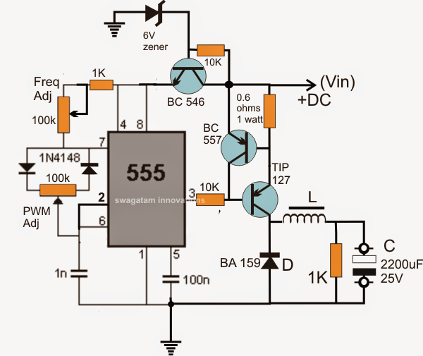
Boost Converter Circuit using 555 Timer IC

Boost Converter Circuit 555

555 Timer Circuits Diagram

Figure 2 from Simple boost converter using Timer IC 555 for charging

Astable 555 Timer Calculator