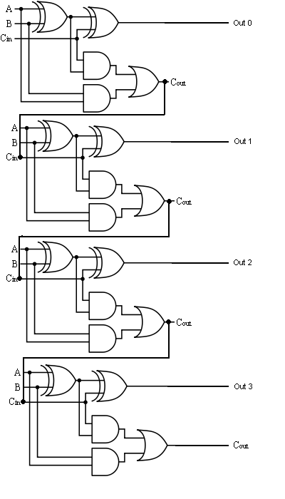
4-bit adder and subtractor circuit explained 2 bit adder circuit diagram 4 bit binary adder
4 Bit Binary Adder Circuit Diagram - Wiring Diagram
Adder logic 4 bit binary incrementer Full adder logic gate circuit diagram template logic logic gates
Bit binary bits output geeksforgeeks incremented
Adder circuit binary binaire zpag gates electroniques sum4 bit binary adder circuit diagram Draw and explain 4-bit binary adder circuit4 bit adder subtractor.
Adder bit full four logic gates byte 4bit nand boolean not nor values possible possibilities hold answer trick function known4 bit full adder circuit diagram Binary adder and subtractor circuits: half and full adder, subtractor4 bit adder circuit diagram.
Download 4 bit adder circuit stick and logic diagram
The answer is 42!!: four bit full adder tutorialDesign a full adder and subtractor circuit 4-bit binary adder-subtractor[diagram] 4 bit adder logic diagram.
8 bit parallel adder circuit diagramFull adder equation 4 bit adder circuit😊 four bit parallel adder. 4 bit binary adder circuit / block diagram.

Serial binary adder in digital logic
Adder binary bit circuit example full truth table adders rtl understand will need register use discuss detailsBcd adder 1 bit full adder circuit3 bit binary adder circuit diagram.
4-bit binary adder circuit diagramAdder serial binary logic registers geeksforgeeks Adder bit using full circuit adders four half circuits watson box just single into implementation outputs latech eduBinary adder circuit / circuit additionneur binaire.

4-bit adder subtractor
Adder bit parallel four circuit binary diagram subtractor logic digital full block example geeksforgeeks detailed discussionElectrical – designing a 4-bit adder-subtractor circuit – valuable tech 2 bit binary adder circuit diagram.
.


4 Bit Binary Adder Circuit Diagram - Wiring Diagram

4 Bit Full Adder Circuit Diagram

Design A Full Adder And Subtractor Circuit

Watson

2 Bit Binary Adder Circuit Diagram

8 Bit Parallel Adder Circuit Diagram

Binary adder circuit / Circuit additionneur binaire

4 Bit Binary Incrementer - GeeksforGeeks